|
<< Click to Display Table of Contents >> Material Interfaces |
  
|
|
<< Click to Display Table of Contents >> Material Interfaces |
  
|
At a material interface, Maxwell’s equations require that the tangential components of ![]() and
and ![]() and the normal components of
and the normal components of ![]() and
and ![]() must be continuous.
must be continuous.
The tangential continuity of components ![]() and
and ![]() is automatically satisfied, because FlexPDE stores only a single value of variables at the interface.
is automatically satisfied, because FlexPDE stores only a single value of variables at the interface.
Continuity of ![]() , which is always tangential, requires, using (3.12),
, which is always tangential, requires, using (3.12), ![]() .
.
Continuity of ![]() requires
requires  .
.
At internal boundaries, and in the absence of Natural specification, FlexPDE will consider the quantities represented by the Natural BC to be continuous.
From (3.16) it is clear that at vertical interfaces, the continuity of ![]() will be satisfied by the
will be satisfied by the![]() equation, while for horizontal interfaces, it will be satisfied by the
equation, while for horizontal interfaces, it will be satisfied by the ![]() equation.
equation.
If all material discontinuities occur at vertical faces and ![]() is piecewise constant, we can multiply the
is piecewise constant, we can multiply the ![]() equation by
equation by ![]() , and continuity of
, and continuity of ![]() will be satisfied. Similarly, if all material discontinuities occur at horizontal faces and
will be satisfied. Similarly, if all material discontinuities occur at horizontal faces and ![]() is piecewise constant, we can multiply the
is piecewise constant, we can multiply the![]() equation by
equation by ![]() , and continuity of
, and continuity of ![]() will be satisfied.
will be satisfied.
Clearly, at an internal interface where ![]() is continuous, the internal natural boundary condition reduces to zero, which is the default condition.
is continuous, the internal natural boundary condition reduces to zero, which is the default condition.
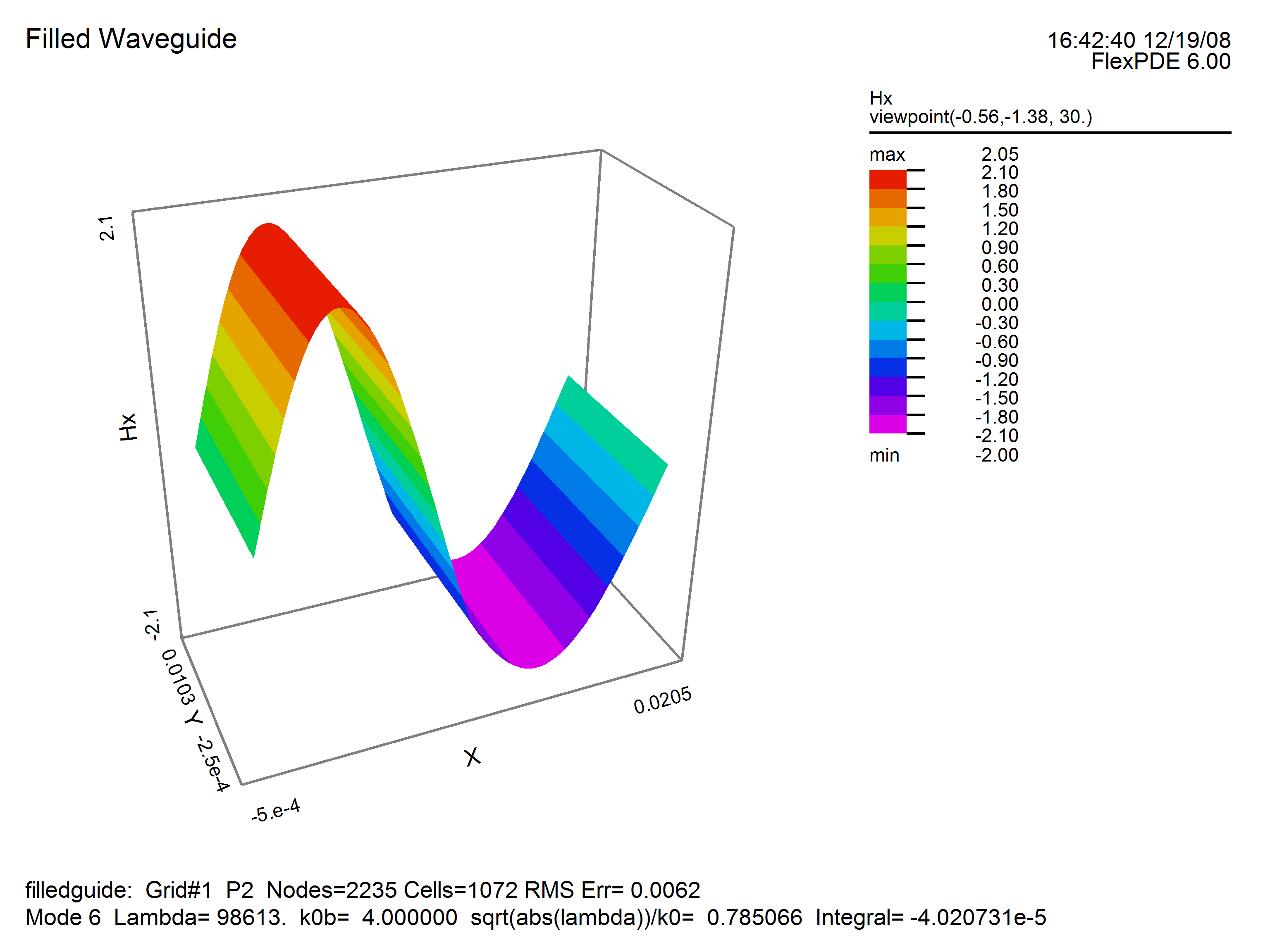
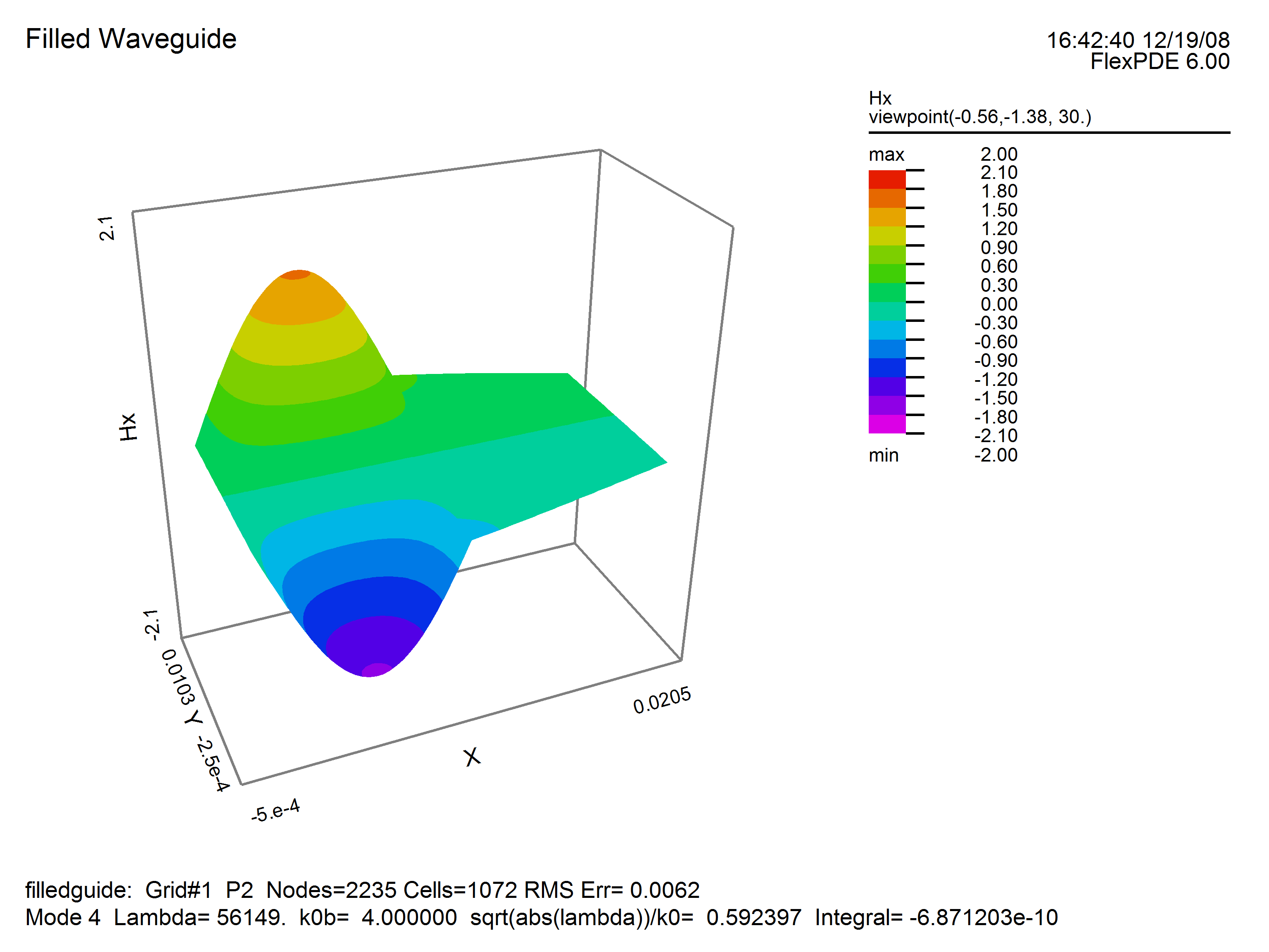
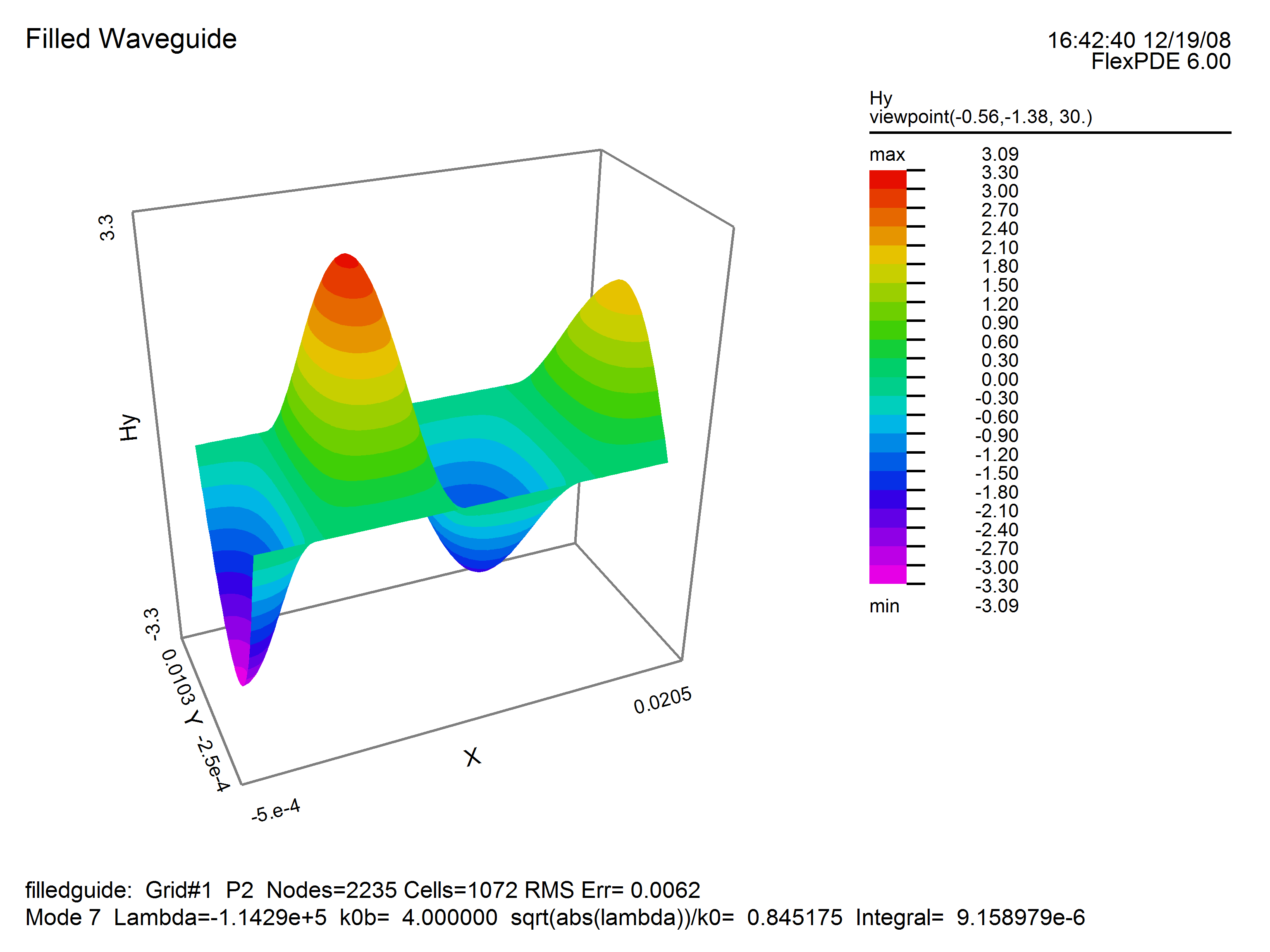
In the example which follows, we consider a simple 2x1 metal box with dielectric material in the left half. Note that FlexPDE will compute the eigenvalues with lowest magnitude, regardless of sign, while negative eigenvalues correspond to modes with propagation constants below cutoff, and are therefore not physically realizable.
See also "Samples | Usage | Eigenvalues | Filledguide.pde"
title "Filled Waveguide"
{ This problem is taken from Fernandez and Lu,
"Microwave and Optical Waveguide Analysis by the Finite Element Method" page 138. }
select
modes = 5 { This is the number of Eigenvalues desired. }
ngrid = 30
overshoot = 1e-9 { request very tight Conjugate Gradient convergence }
variables
Hx, Hy
definitions
cm = 0.01 ! conversion from cm to meters
b = 1*cm ! box height
L = 2*b ! box width
epsr ! values will be given by region
epsr1=1 epsr2=1.5
eps0 = 8.85e-12
mu0 = 4e-7*pi
c = 1/sqrt(mu0*eps0) ! light speed
k0b = 4 ! normalized driving frequency
k0 = k0b/b
k02 = k0^2 ! k0^2=omega^2*mu0*eps0
! terms used in equations and BC’s
curlh = dx(Hy)-dy(Hx)
divh = dx(Hx)+dy(Hy)
! the solution generates some negative eigenvalues, so we shift the eigenvalues to a range where only the
! positive values appear
shift = 200000
true_lambda=lambda+shift
! extract the propagation wave number kz
kz = if(true_lambda>0)then sqrt(true_lambda) else -sqrt(abs(true_lambda))
equations
! Hx equation multiplied by epsr to enforce continuity of Hz
Hx: dx(divh) - dy(curlh) + k02*Hx*epsr - (lambda+shift)*Hx = 0
Hy: dx(curlh/epsr) + dy(divh)/epsr + k02*Hy - (lambda+shift)*Hy/epsr = 0
boundaries
region 1 epsr=epsr1
start(0,0)
natural(Hx) = 0 value(Hy)=0
line to (L,0)
value(Hx) = 0 value(Hy)=0 natural(Hy)=0
line to (L,b)
natural(Hx) = 0 value(Hy)=0
line to (0,b)
value(Hx) = 0 natural(Hy)=0
line to close
region 2 epsr=epsr2
start(b,b)
line to (0,b) to (0,0) to (b,0)
line to close
monitors
contour(Hx) range=(-1,1)
contour(Hy) range=(-1,1)
plots
contour(Hx) range=(-1,1) report(k0) report(kz)
surface(Hx) range=(-1,1) report(k0) report(kz)
contour(Hy) range=(-1,1) report(k0) report(kz)
surface(Hy) range=(-1,1) report(k0) report(kz)
surface(divh) range=(-1,1) as "Hz" report(k0) report(kz)
surface(curlh/epsr) range=(-1,1) as "Ez" report(k0) report(kz)
summary export
report lambda
report shift
report true_lambda
report(k0)
report( if(true_lambda<0) then "*" else " ") ! mark negative eigenvalues
report(kz)
report(kz/k0)
end


