|
<< Click to Display Table of Contents >> free_plate |
  
|
|
<< Click to Display Table of Contents >> free_plate |
|
{ FREE_PLATE.PDE
This example considers the bending of a thin rectangular plate under a
distributed transverse load.
For small displacements, the deflection U is described by the Biharmonic
equation of plate flexure
del2(del2(U)) + Q/D = 0
where
Q is the load distribution,
D = E*h^3/(12*(1-nu^2))
E is Young's Modulus
nu is Poisson's ratio
and h is the plate thickness.
The boundary conditions to be imposed depend on the way in which the
plate is mounted. Here we consider the case of a simply supported
boundary, for which the correct conditions are
U = 0
Mn = 0
where Mn is the tangential component of the bending moment, which in turn
is related to the curvature of the plate. An approximation to the second
boundary condition is then
del2(U) = 0.
FlexPDE cannot directly solve the fourth order equation, but if we
define V = del2(U), then the deflection equation becomes
del2(U) = V
del2(V) + Q = 0
with the boundary conditions
U = 0
V = 0.
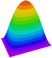
The particular problem addressed here is a plate of 16-gauge steel,
8 x 11.2 inches, covering a vacuum chamber, with atmospheric pressure
loading the plate. The edges are simply supported. Solutions to this
problem are readily available, for example in Roark's Formulas for Stress
& Strain, from which the maximum deflection is Umax = 0.746, as compared
with the FlexPDE result of 0.750.
(See FIXED_PLATE.PDE for the solution with a clamped edge.)
Note: Care must be exercised when extending this formulation to more complex
problems. In particular, in the equation del2(U) = V, V acts as a source
in the boundary-value equation for U. Imposing a value boundary condition
on U does not enforce V = del2(U).
}
Title " Plate Bending - simple support "
Select
ngrid=10 { increase initial gridding }
cubic { Use Cubic Basis }
Variables
U(0.1)
V(0.1)
Definitions
xslab = 11.2
yslab = 8
h = 0.0598 {16 ga}
L = 1.0e6
E = 29e6
Q = 14.7
nu = .3
D = E*h^3/(12*(1-nu^2))
Initial Values U = 0 V = 0
Equations U: del2(U) = V V: del2(V) = Q/D
Boundaries Region 1 start (0,0) value(U) = 0 value(V) = 0 line to (xslab,0) to (xslab,yslab) to (0,yslab) to close
Monitors contour(U) |
|
Plots
contour (U) as "Displacement"
elevation(U) from (0,yslab/2) to (xslab,yslab/2) as "Displacement"
surface(U) as "Displacement"
End