|
<< Click to Display Table of Contents >> TRANSFER6 File format |
  
|
|
<< Click to Display Table of Contents >> TRANSFER6 File format |
|
The format of a TRANSFER6 file is identical to the version 6 output format, and contains the following data.
The Header Section
1) A header containing an identifying section listing the FlexPDE version, generating problem name and run time, and plotted variable name or function equation. This header is enclosed in comment brackets, { ... }.
2) A file identifier "FlexPDE transfer file", and the problem title.
3) The number of geometric dimensions and their names.
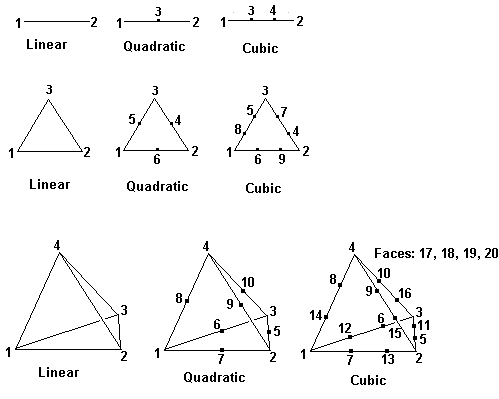
4) The finite element basis identifier from 4 to 10, meaning:
•4 = linear triangle (3 points per cell)
•5 = quadratic triangle (6 points per cell)
•6 = cubic triangle (9 points per cell)
•7 = cubic triangle (10 points per cell)
•8 = linear tetrahedron (4 points per cell)
•9 = quadratic tetrahedron (10 points per cell)
•10 = cubic tetrahedron (20 points per cell)
5) The number of degrees of freedom (points per cell as above).
6) Current problem time and timestep (time-dependent problems only).
7) The number of output variables and their names
8) The number of domain joints (boundary break points) and their descriptions, including
•Joint number
•Periodic image joint (or 0)
•Associated global node number
•Extrusion surface (or 0)
•Active flag
9) The number of domain edges and their descriptions, including
•Edge number
•Associated base plane edge number
•Beginning joint number
•Ending joint number
•Periodic image edge (or 0)
•Extrusion surface (or 0)
•Extrusion layer (or 0)
•Active, Feature and Contact flags
•Edge name
10) The number of 3D domain faces and their descriptions, including
•Face number
•Associated base plane face number
•Left adjoining Region number
•Right adjoining Region number
•Periodic image face (or 0)
•Shape selector
•Layer or surface number
•Active and Contact flags
•Face name
11) The number of domain regions and their descriptions, including
•Region number
•Associated base plane region number
•Layer (or 0)
•Material number
•Active flag
•Region name
The Data Section
Each distinct material type in the exported problem is represented by a separate section in the TRANSFER file. Material types are defined by matching parameter definitions. Each data section consists of:
1) The number of nodes
2) The nodal data, containing one line for each node with the following format:
•two or three coordinates and as many data values as specified in (7).
•a colon (:)
•the global node index
•the node type (0=interior; 1=joint; 2=edge; 3=face; 4=exterior)
•the type qualifier (region number, joint number, edge number or face number)
•the periodic node index
3) The number of cells.
4) The cell connectivity data, one line per cell, listing the following:
•the geometric basis (as in Header 4)
•the node numbers (local to the current material block) which comprise the cell. The count of these node numbers is controlled by (Header 5).
•a colon (:)
•the global cell number
•the logical region number
•the material number
The node numbers are presented in the following order: