|
<< Click to Display Table of Contents >> Generating A Mesh |
  
|
|
<< Click to Display Table of Contents >> Generating A Mesh |
|
When you select "Run Script" from the Controls menu (or the ![]() button), FlexPDE will begin execution by automatically creating a finite element mesh to fit the domain you have described. In the automatic mesh, cell sizes will be determined by the spacing between explicit points in the domain boundary, by the curvature of arcs, or by explicit user density controls.
button), FlexPDE will begin execution by automatically creating a finite element mesh to fit the domain you have described. In the automatic mesh, cell sizes will be determined by the spacing between explicit points in the domain boundary, by the curvature of arcs, or by explicit user density controls.
In our example, the automatic mesh looks like this:
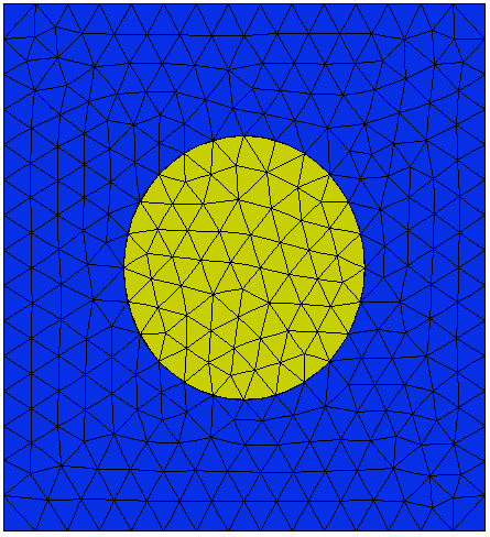
Notice that the circular boundary of region 2 is mapped onto cell legs.
There are several controls that the user can apply to change the behavior of the automatic mesh. These are described in detail in the chapter "Controlling Mesh Density" below.
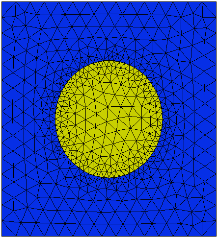
As an example, we can cause the circular boundary of region 2 to be gridded more densely by using the modifier MESH_SPACING:
REGION 2 'blob' { the embedded 'blob' }
START(1/2,0)
MESH_SPACING = 0.05
ARC(CENTER=0,0) ANGLE=360
The resulting mesh looks like this:
In most cases, it is not necessary to intervene in the mesh generation, because as we will see later, FlexPDE will adaptively refine the mesh wherever it detects that there are strong curvatures in the solution.